Welcome to Smart Home Forum by FIBARO
Dear Guest,
as you can notice parts of Smart Home Forum by FIBARO is not available for you. You have to register in order to view all content and post in our community. Don't worry! Registration is a simple free process that requires minimal information for you to sign up. Become a part of of Smart Home Forum by FIBARO by creating an account.
As a member you can:
- Start new topics and reply to others
- Follow topics and users to get email updates
- Get your own profile page and make new friends
- Send personal messages
- ... and learn a lot about our system!
Regards,
Smart Home Forum by FIBARO Team
Search the Community
Showing results for tags 'smart implant'.
-
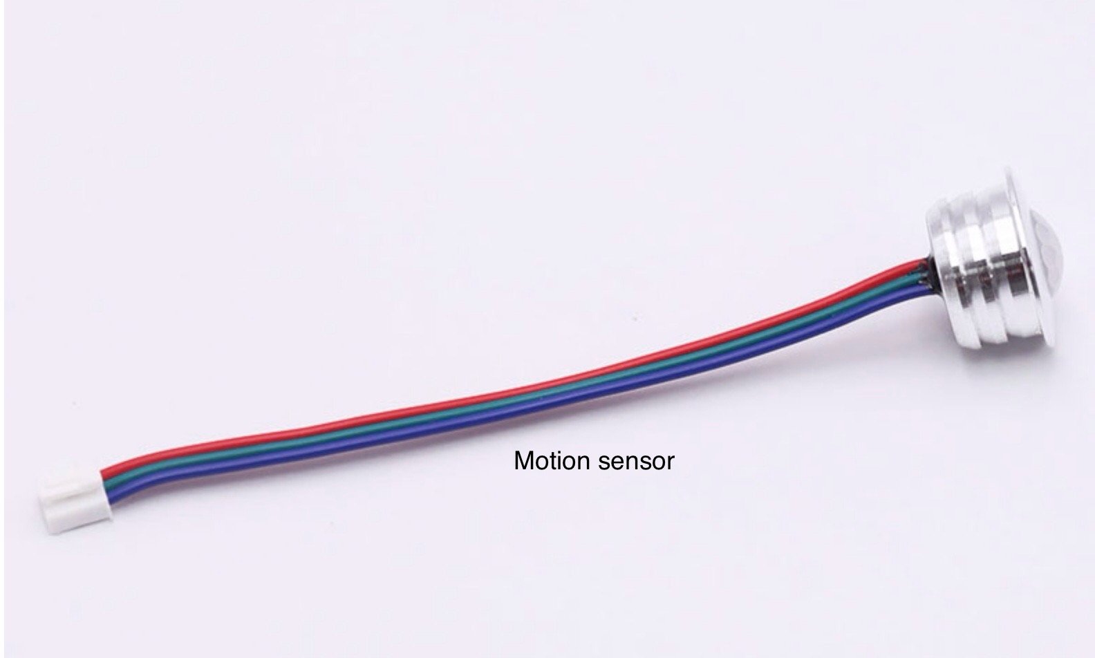
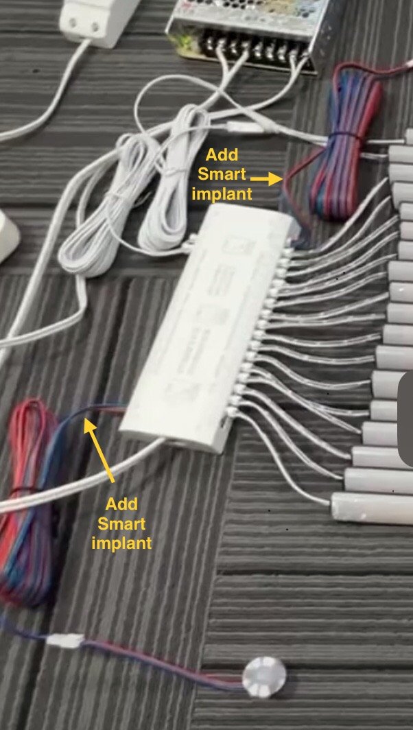
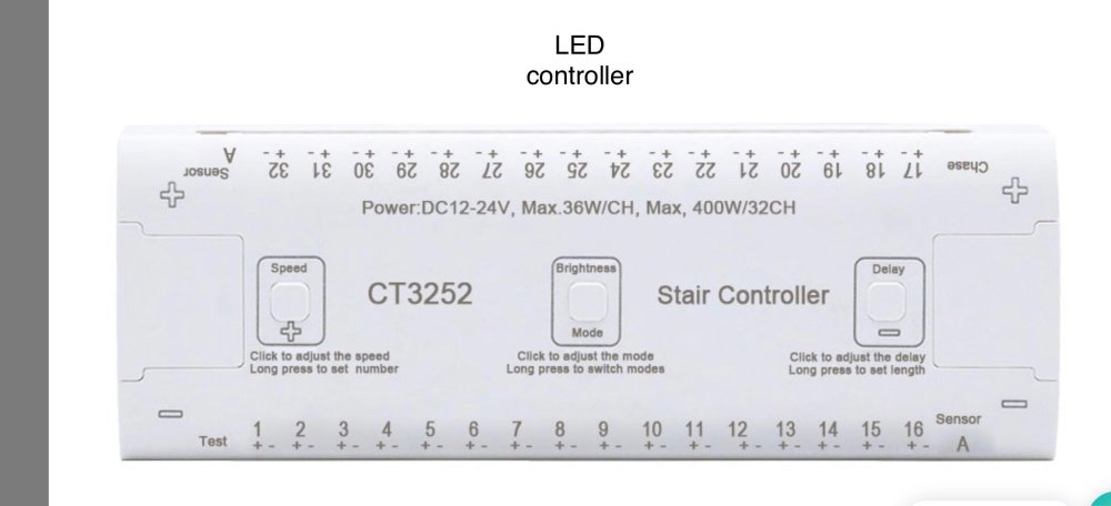
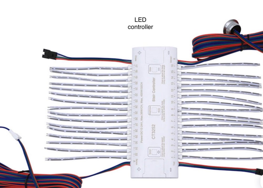
 I installed cascading LED lights on my stair case that is activated with PIR 3 wire motion sensors. My problem is when I walk up stairs the bottom sensor triggers the upward flow of the lights but when I cross the top sensor it triggers the downward flow so they run at the same time. I currently have SmartThings (but will be upgrading to Homey soon) and would like to use smart implants between the sensor and the light controller to switch off the top sensor temporarily when the bottom sensor is triggered and visa versa. Would smart implants work? If so how would I wire them? System specifics: DC12V 200 watt power supply 12V LED light controller CT3252 3 wire PIR motion sensor Thank you!


-
Hi, I connected the binary sensor for the door sensor but the icon is representing the door. I want to change the icon. How I can do this?
-
Hi everyone, I have connected to my Smartimplant 0-10V sensors, now I get numbers of Volts, but I would like to see it in percentage, and even better would be, if I could set how much volts are 100%. Is there any way to do so? Thanks for advice. David
-
Hi Everyone, Newbie here. I have successfully installed a smart implant to control by garage door. It acts as a push button. My problems: 1 - I would like to have the HC3 web interface (or yubi) to display a push (momentary) switch icon instead of a on/off switch icon, is it possible? 2 - I only have a small number of available icons in HC3, for exemple I can select for my smart implant a bulb icon or a siren icon, but not a garage door icon. Is there a way to solve this? 3 - Last but not least, I would like to get information about when the garage door is open and when it is closed, without using any existing hardware. I imagine that it could be possible to have some kind of seen or quick app that would do the following: - set up a variable somewhere called "status" - when switch is activated the first time set status to 1, when it is activated the second time it sets the status to 0, and so on... is there an easy way to do this and get some kind of icon displaying the status of the garage door? Thank you in advance

-
Is it not possible to perform the latest firmware update without a Fibaro hub? Is there a link somewhere to the new firmware? Usually manufacturers provide a file and updates can be done even with a simple generic z-wave stick. I have both a Zooz Z-Wave Plus S2 USB Stick as well as a Aeotec Z-Stick Gen5 which I've used in ths past for other updates for various manufacturers.
-
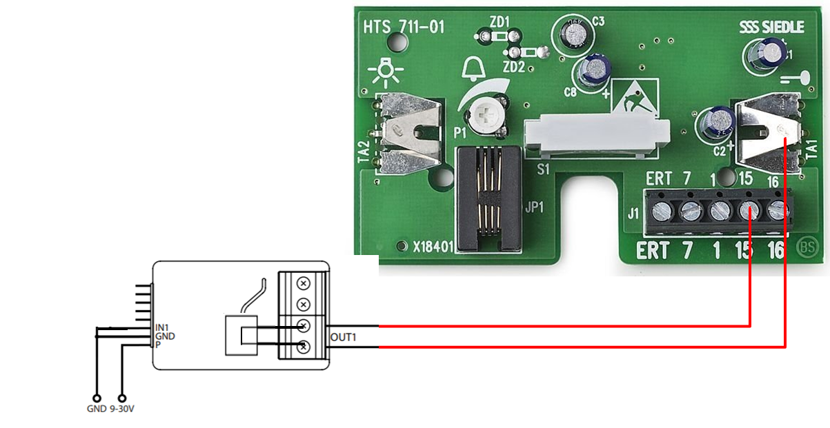
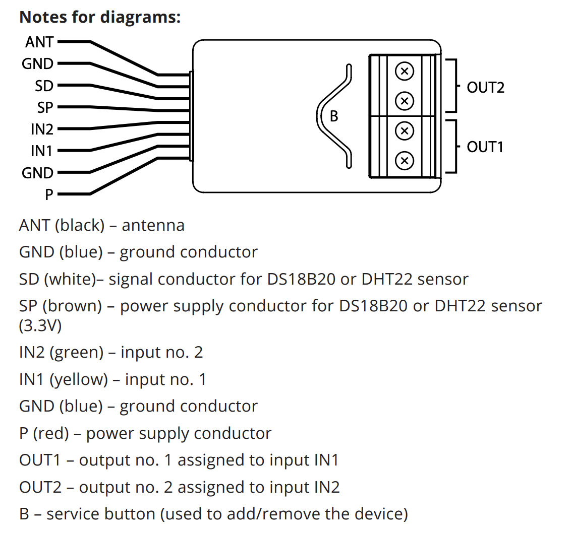
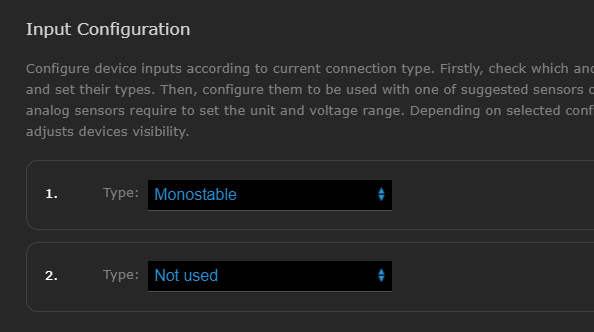
 I had two Zipato RFID Readers. Both died nearly at the same time So there is no other RFID Reader with Z-Wave support available. Because of this I had to use a "normal" one and connect it to my HC2. One disadvantage is that I won't know which PIN code or which RFID has been used during last login! Here is my description how I did set it up. Maybe others will need this information too or somebody else has some improvements (mostly according the Fibaro Smart Plant). I am pretty sure that @petergebruers has some improvements for me I did search in the web for any solutions but could not find anything useful. Most persons did ask how to wire it properly and did not come up with a working solution or some others explained that it is working...but not how why have done it. So what is needed: I am using the new Fibaro Smart Plant FGBS-222, any RFID/PIN/Fingerprint Codepanel and a power supply. You can use a normal one (between 6V and 24V) or a special one for the codepanel if a bell, door lock, additional switch or something else should be used also. I did connect power to the codepanel (DC+) and to the Fibrao Sensor (P, red wire) and ground with Fibaro (GND, blue wire) and twice with the codepanel (GND and COM). Also I did connect the alarm wire of the codepanel with IN2 (green wire) of the Fibaro module and the NO wire of the codepanel with IN1 (yellow wire) of the Fibaro module. (Later on I will do some drawing). To make this working you will have to change the settings of the Fibaro module. For me it was working by using the scene activation. For this I did set up input 1 and 2 as mono stable (I think this is parameter 20 and 21), did put HC2 in associative group 2, disabled the two output connections (you don't have to do this I think), enabled "Key pressing and holding" for Input 1 and 2 (alias parameter 40 and 41) and that's it. Than you will have to write two scenes. Both should react on the scene child module of the Fibaro Smart Implant for the action "Key [1|2] HeldDown". Key 1 will get triggered if somebody authenticated successfully and key 2 will get triggered if the alarm (e.g. somebody tries to open the case) goes on. My use case will be to open the garage door or open the cellar door by entering the proper ID or using the right RFID chip.
 -
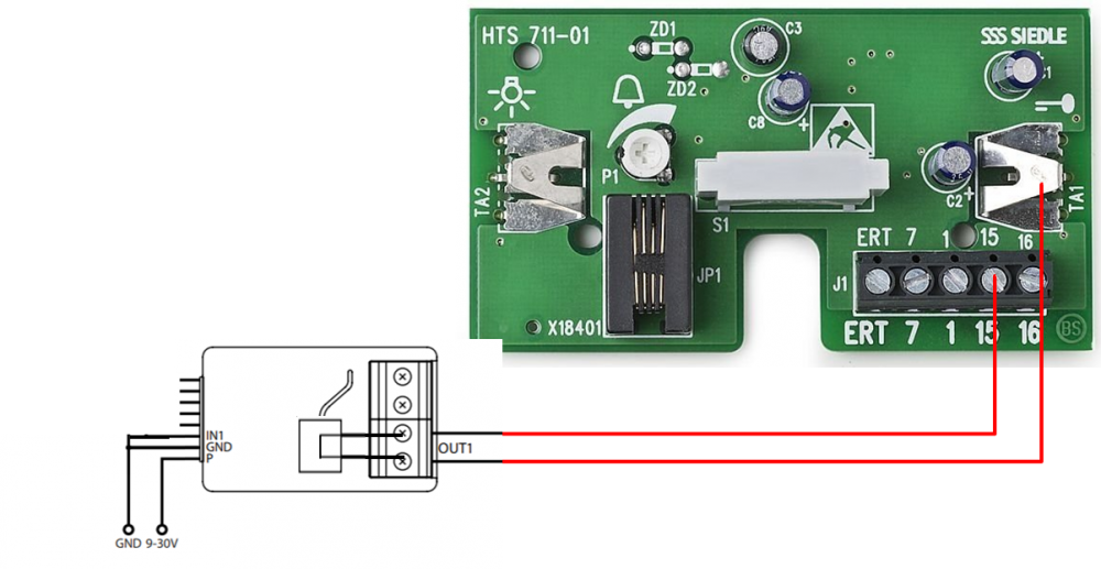
Hi, I've the classic doorbell and I should like to know the automatization of the doorbell when the doorbell is played I create action in my Fibaro HCL but I don't know if Fibaro single switch is recommended with the doorbell or need another device by Fibaro?
-
 The Smart Implant can have up to 6 temperature sensors added to it, which makes it handy for climate control applications. Here is a guide based on my experience, hopefully it helps you avoid the frustrations I had. 1. Buy the sensors from a reputable source. The DS18B20 is manufactured by Maxim Integrated (ex-Dallas Semiconductor). There are many counterfeit sensors out there (eg Chinese company CXGAS) that either will simply not work, report incorrect readings, or stop working after a short period. If the sensor is built into a probe it can be difficult to determine a counterfeit unless you open the casing, which can be difficult due to epoxy encapsulation. It seems most sensors bought on eBay, Aliexpress, Banggood etc are counterfeit. See more on this here: https://forum.fibaro.com/topic/49944-if-you-did-not-buy-your-ds18b20-from-a-reputable-source-it-is-probably-a-clone-and-may-have-issues/ 2. Keep the length of the lead between sensor and device under 3 meters, otherwise there may be synchronisation errors. 3. A 4.7k resistor is required as a pullup from the DATA to VCC line. If the DS18B20 is built into a probe, the resistor is probably not included. 4. Where the DS18B20 device is soldered to a small daughter board, be careful as the PCB tracks may not connect directly to the corresponding jumper pins – instead the connections may be rearranged. Use a multimeter to confirm the pinout. 5. Up to six sensors can be used, connected in parallel. The leads should all be the same length, to ensure the signals stay synchronised. Regardless of the number of sensors, a single 4.7k resistor is required as a pullup from the DATA to VCC line. In order to show the temperature device slaves in your Home Center devices screen: 1. Power down the device 2. Wire the sensor(s) up, including the resistor 3. Move the Smart Implant very close to the Home Centre 4. Power up and click the “Reconfigure Device” button in advanced options. 5. You will need to delete the device and re-add it if you have changed sensors, as the internal sensor serial number identifiers will have changed. 6. The temperature sensors will appear as additional Slaves. When attempting to add the device, if you receive the error message: "ID xx: System hardware failure. Read the manual", this is a good indicator you have a clone sensor. Set Parameters 67 and 68 as required, so that regular temperature reports are sent. Note that the Smart Implant contains an internal temperature sensor. This is likely to over-report air temperature, because the sensor is located inside the device and that will make it slightly warmer. If this guide helped you, click the Heart symbol below to say thanks.
 -

Smart implant w sygnalizatorze np SPLZ-1011 R - alarm
piowla posted a question in Urządzenia Firm Trzecich
Witam. Mam pytanie. Czy jest możliwość podpięcia smart implantu do sygnalizatora alarmu SPLZ-1011 R w taki sposób aby zasilanie sygnalizatora posiadającego wewnętrzny akumulator było zasilaniem smart implantu, a dokładnie aby smart implant był w razie wyłączenia prądu zasilany awaryjnie również z akumulatora sygnalizatora. Niestety nie znalazłem schematu tego sygnalizatora i nie wiem czy to możliwe. Czy miejscem, gdzie należy się wpiąć z implantem w sensie jego zasilania to miejsce równoległe do zasilania akumulatora tego sygnalizatora? -
Witam potrzebuję pomocy jak zrobić aby oprogramować długie przytrzymanie ze smartimplant na wejściu INT1 tak aby wymusić zadziałanie Realy switch 2x1,5 tylko pierwszy kanał mam zaznaczone w parametrach Smart-a opcję Parametr 40: Wejście IN1 - aktywacja scen kanał i jest ustawione wciśnięte i przytrzymane po prawej wyświetla się cyfra "8" Deklaracje { conditions = { { id = 147, isTrigger = true, operator = "==", property = "centralSceneEvent", type = "device", value = { keyAttribute = "holddown", keyId = 8 }}}, operator = "all" } Akcje fibaro.call(152, 'turnOn')
-
I am trying to connect the smart implant to an alarm with 12v outputs to signal "alarm armed" and "alarm active" (i.e. breach identified). I connected the SI using the inputs as analog. I can see the correct voltage on the analog inputs (i.e. +12v = armed / 0v = unarmed). But I can't make the smart implant to generate events (i.e. open/closed/switched) when the voltage changes. I can only poll the voltage periodically to check if it has changed. I have already fiddled wit parameters 63 (input threshold) and 64 (periodical report) with no success. What is the right way to generate events when the voltage changes from 0 to 12v? Thanks Roberto
-
Hello, I have a Fibaro Smart Implant and was wondering if you can explain some strange behavior I'm seeing. I have binary sensors connected to IN1 and IN2, with this configuration: parameters 20 and 21 set to 0 (normally closed) parameters 150 and 151 set to 10 (100ms) parameters 152 and 153 set to 0 (no delay) The problem is, if I leave the contacts open for a period of time, the implant will report they are closed after exactly 1 hour (3600 seconds). I have tested multiple times with multiple implants. Thanks for your help, Ovidiu
-
Hello, my garage door motor is a marantec comfort 220.2. I’m considering adding on it a smart implant. Did anyone do it before? Do you have wiring diagrams and photos? Any help, hint or guidance is welcome. Thanks.
-

Scenarion for ARM/DISARM using a Smart Implant
bogdancautisanu posted a question in Scenes and Interface
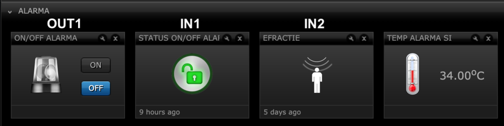
Dear gentleman, I have a problem with making a scene for ARM/DISSAR the system using the smart implant. I want to mention that my alarm system it is not a smart one. I will describe what I have done till now. I installed 2 relay on the alarm PGM exits to know the status of the system and to have a feedback if the alarm is activated. I use the smart implant as follow: 1. The OUT1 is connected to the ON/OFF impulse in order to ON and OFF the system. Each impulse will ON or OFF the system 2. The IN1 is connected as switch on the ARM/DISARM status. Basically if the relay it is open the system is DISARM and if relay is closed the system is ARM. 3. The IN2 is connected as switch for the thief alarm. Basically if the system it is ARMED and someone enter in the house this relay will be CLOSED and get a feedback. Relay = ON - ALARM and relay = OFF - NO ALARM Till now it is ok and it is works. My question is the scene. I did not succeed to make a correct scene. What I want to make it is next: 1. ARM the SYSTEM scene 2. DISARM the system scene To ARM the SYSTEM i've made a scenario like: if IN1= breached then OUT1 = On ... and the fibaro arm the system. To DISARM the SYSTEM it is similar - if IN1= safe then OUT1 = On the problem is that the system goes in to a loop. To avoid that I put a one time trigger like - OnceEg. Run Scene on 23/4/2024 at 12:30 at beginning of each scene. So in this case the system will not go on the loop but it seems that there is a mistake in my logic scheme because the if I run DISARM scene even if the IN1 is safe (meaning that the system it is already disarmed) the OUT1 give the ON impulse and arm the alarm. Please guys, be so kind and give me a solution. Thank you.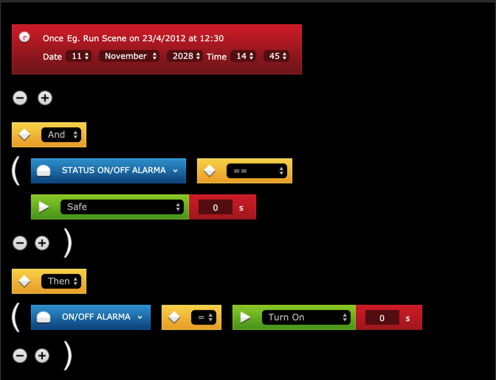

-
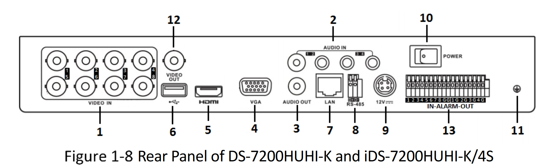
Hi all... I have purchased a Smart Implant to add to my HC2 so that I can capture the Alarm Output from my Hikvision DVR. The aim of this exercise is to capture the alarm breach from my DVR when someone crosses my drive which is monitored by a CCTV camera. The camera is setup to generate a alarm output signal which I believe can be captured by Smart Implant and trigger an action on HC2. I have successfully included the Smart Implant into HC2. I have connected the cable marked IN1 to Alarm 1 Output and GND cable to G 1 Output on the DVR. However, it is not picking up anything. Have I connected the correct cables?? Thanks in advance.


-
Greeting everyone, I 've got stuck with the strange behavior of smart implant which I couldn't explain other as a bug. I have Z-Stick from Aeotec and wanted to configure my smart implant to send periodic reports from smart implant by schedule (every 60 seconds). So, I've changed the configuration parameter 66 to 60 as it stated in documentation and started to wait.... After a while nothing happens. The same time when I ask multisensor to send me a temperature report, I can get it without any problem. So, I tried to experiment with another automated reports. I have configured automated reports about voltage level on IN1 & IN2, this doesn;'t work.... I have attached external temperature senor and asked to send automatic reports from their - doesn't work. However when I am trying to read it directly from corresponding sensors - everything working fine but no automatic reports at all. The same time when I am using Aeotec Multisensor I can easily to see updates from all 4 internal sensors. Does anybody faced with the same behavior? IMHO, either I am doing something completely wrong and Fibaro have to provide better documentation or this is a strange bug in the device. I have sent my escalations to Fibaro but didn't get any news yet. I am not using any home automation software, just only Z-Wave PC Controller 5 from Sigma Design. This allows me to send commands on a low level which completely exclude any potential issues in mappings of UI with real commands have to be sent to device.
-
Greetings, I have a situation with Smart Implant. I would like to connect my Paradox alarm system and I am it next point: - I succeed to connect the smart implant (SI) to the system and arm and disarm the system through the Home Center panel. Basically I powered the SI and use OUT 1 for on/off alarm system. My questions are : 1. what should I do (wiring) in order to see in the Home Center panel if the system is armed or not? 2. what should I do (wiring) in order to get a notification if the alarm is triggered? Thank you very much for your support. Bogdan
-
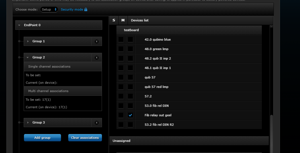
Hi , I look to use a "smart implant " to connect an alarm system intelligently to my Zwave network ( Use light flashing for a smoke alarm) I don't plan to use scenes but rather the "association " method I built a test set up where the smartimplant is fed with 9v DC , input 1 (IN1) goes to momentary switch. Goal is to light a yellow bulb when there is an contact closure on IN1 ( IN1 is configured as NO , binary input) It is associated to a Fibaro dual relay module , output 1 ( with yellow Bulb) Association is done in Multichannel mode: The association does not work Other setups using associations do work ( univ sensor with smart plugs, qubino relays with fibaro relays , fibaro dimmers between each other ...) so , why is this one not working? what is configured wrong? additional : what is the meaning of the "Security mode " [ in blue , top of screen ] ? is this a sign of encrypted comms ? if so , do other devices accept hte comms from the smart implant thanks for your support Geert edit : question resolved . A device in security mode can not be associated to a device in non-security mode. For smart implant , the mode is defined at moment of inclusion or [adding the device]
-
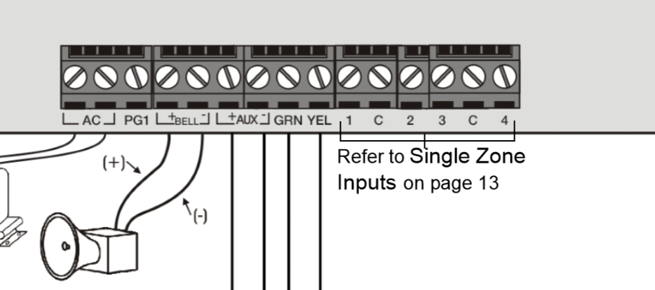
 Hi, I have a FGBS-222 smart implant, Paradox NV5 motion sensor and a SP4000 paradox alarm control board attached to paradox K636 key pad. The problem is how do connect the wiring from the motion sensor to the smart implant and from the smart implant back to the alarm control board?? above it the NV5 motion sensor terminals. Above is the terminal for the SP4000 alarm control board. Last but not least the smart implant terminal. Below is my wiring connection. I am able to control the output of the fibaro smart implant from the fibaro home center lite however, the smart implant cannot detect the output of the motion sensor. Any suggestion to modify?? Aside question, is fibaro smart implant able to arm or disarm a alarm system??. Thank you. FGBS-222-EN-T-v1.0 (Smart inplat).pdf MGSP-EI15 SP4000.pdf NV5_Installation_Manual(motion sensor).pdf User-Manual-Paradox-Spectra-K636-LED-alarm-keypad.pdf
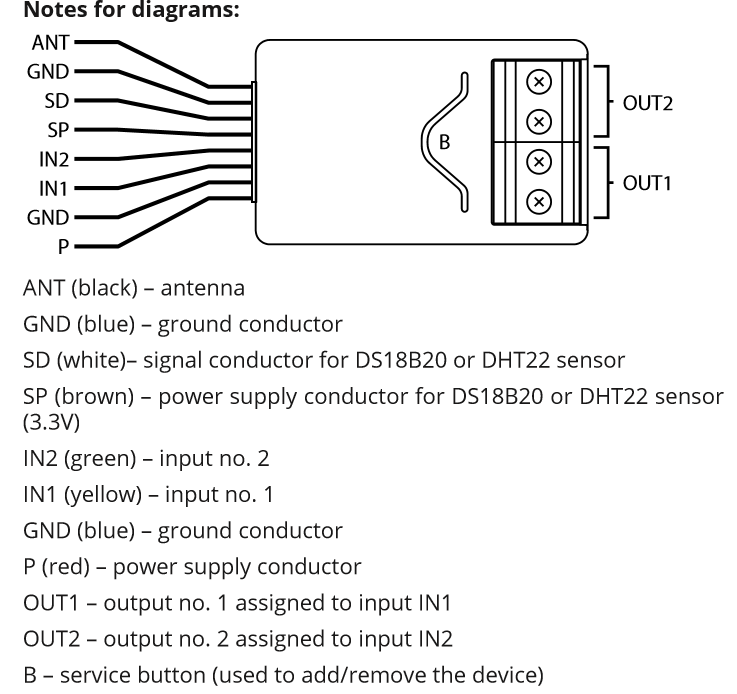

-
Hi there, I just purchased a Smart Implant to connect my smoke detector and carbon monoxide alarms to my SmartThings system. Before I try to write a Device Handler to make it work, does anyone already have a Smart Implant Device Handler they would be willing to share? Thanks, Ben
- 7 replies
-
- 3
-

-
- smartthings
- smart implant
- (and 1 more)
-
I have a question I would like icons from IN1 to appear; IN2; out1; out2; regardless, I would like to see in turn what state I have at the individual entrance exits. I need this for another company's alarm, I would like to control the zone and be able to connect to disconnect the zone. Is it possible? Ok, I have already found my oversight, I need to switch to ON in access protection.

-
Mam pytanie chciałbym by pojawiły sie ikony od IN1; IN2; Out1; Out2; niezależnie, chciałbym widzieć kolejno, jaki mam stan na poszczególnych wejściach wyjściach. Jest mi to potrzebne do alarmu innej firmy, chciałbym kontrolować strefę oraz móc załączac rozłączać strefę. Czy jest to możliwe? Rozwiązałem, moje przeoczenie. Ok, już znalazłem moje przeoczenie, muszę przełączyć się na ON w ochronie dostępu

-
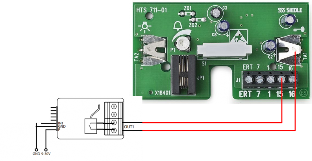
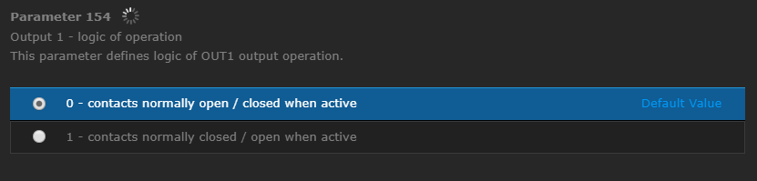
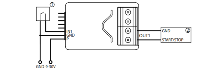
Dear Fibaro Community. I`m trying to use the new Fibaro “Smart Implant” to close the NO-contact of my gate opener . For this case the Fibaro manual suggests this wiring diagramm: My gate has a NO (normall open) contact that needs to be closed (connected/bridged) to open the door. hence I configured Parameter 154 to “0” - contacts normally open / closed when active The time these contacts are closed is the time where the gate is open. E.g. (10 seconds for example) Therefore I changed parameter 156 to 10s To my understanding these settings should work as follows: a short “activation” on IN1 triggers both contacts of Output1 to be connected for 10s Now clicking the “ON” button on the Fibaro GUI (graphical user interface) has the desired effect: the contact between the first and second out1 contact is closed and the gate opens for 10s The Problem: It only works via GUI (graphical user interface) Connecting IN1 to GND doesn`t have any effect. The “switch” is not working What am I missing? In a second step i`d like to trigger IN1 with a battery. Therefore I configured it to binary sensor. ->nothing happens What am I missing? Where do I configure the activation voltage and so on? What are the values that IN1 accepts? In short: how can I put something into IN1 to trigger the outputs? regards, Maki Ps: i also get this weird notification that the device is waiting for syncronization :S HC2 v4.540


-
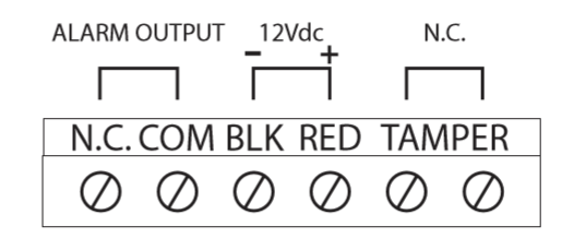
I want to connect my normal alarm with my Fibaro Homecenter 2. I think the Smart Implant can do the trick and I have bought some 12 volt relais to support the Smart Implant because the Smart Implant can’t switch high outputs and is restricted tot 0 - 10 volt. The relais can switch a sabotage loop (normally closed), so the normal alarm will be breached. The functions I first want to achieve are: If my Fibaro Homecenter detects alarm, my normal alarm will be breached and the normal sirene and light signals turn on (etcetera) If my normal alarm is breached, my Fibaro Homecenter will send push messages (etcetera) And in the future I want to: Turn my normal alarm on and off with my Fibaro Homecenter I can give power to the Smart Implant (P red / GND blue) from my normal alarm The relais can also be given power from the normal alarm. The relais has an input with requires a 12 volt signal. Question: How can I give the relais the 12 volt signal with de Smart Implant? Diagram Smart Implant: Relais:


-
At last the Fibaro smart implant is realesed in Sweden, I had a need of controlling a battery powered LED candle so I integrated it in this using the implant powered by a 9v battery and used one of the two outputs to act as a replacement for the switch on the candle, It worked great!...for about 48 hours then the 9v battery was on 3,5v. The problem i think is that smart implant act as a repeater in the z-wave network and it is not open to deactivate the repeating function or am i wrong?