Welcome to Smart Home Forum by FIBARO
Dear Guest,
as you can notice parts of Smart Home Forum by FIBARO is not available for you. You have to register in order to view all content and post in our community. Don't worry! Registration is a simple free process that requires minimal information for you to sign up. Become a part of of Smart Home Forum by FIBARO by creating an account.
As a member you can:
- Start new topics and reply to others
- Follow topics and users to get email updates
- Get your own profile page and make new friends
- Send personal messages
- ... and learn a lot about our system!
Regards,
Smart Home Forum by FIBARO Team
Search the Community
Showing results for tags 'ds18b20'.
Found 17 results
-
 The Smart Implant can have up to 6 temperature sensors added to it, which makes it handy for climate control applications. Here is a guide based on my experience, hopefully it helps you avoid the frustrations I had. 1. Buy the sensors from a reputable source. The DS18B20 is manufactured by Maxim Integrated (ex-Dallas Semiconductor). There are many counterfeit sensors out there (eg Chinese company CXGAS) that either will simply not work, report incorrect readings, or stop working after a short period. If the sensor is built into a probe it can be difficult to determine a counterfeit unless you open the casing, which can be difficult due to epoxy encapsulation. It seems most sensors bought on eBay, Aliexpress, Banggood etc are counterfeit. See more on this here: https://forum.fibaro.com/topic/49944-if-you-did-not-buy-your-ds18b20-from-a-reputable-source-it-is-probably-a-clone-and-may-have-issues/ 2. Keep the length of the lead between sensor and device under 3 meters, otherwise there may be synchronisation errors. 3. A 4.7k resistor is required as a pullup from the DATA to VCC line. If the DS18B20 is built into a probe, the resistor is probably not included. 4. Where the DS18B20 device is soldered to a small daughter board, be careful as the PCB tracks may not connect directly to the corresponding jumper pins – instead the connections may be rearranged. Use a multimeter to confirm the pinout. 5. Up to six sensors can be used, connected in parallel. The leads should all be the same length, to ensure the signals stay synchronised. Regardless of the number of sensors, a single 4.7k resistor is required as a pullup from the DATA to VCC line. In order to show the temperature device slaves in your Home Center devices screen: 1. Power down the device 2. Wire the sensor(s) up, including the resistor 3. Move the Smart Implant very close to the Home Centre 4. Power up and click the “Reconfigure Device” button in advanced options. 5. You will need to delete the device and re-add it if you have changed sensors, as the internal sensor serial number identifiers will have changed. 6. The temperature sensors will appear as additional Slaves. When attempting to add the device, if you receive the error message: "ID xx: System hardware failure. Read the manual", this is a good indicator you have a clone sensor. Set Parameters 67 and 68 as required, so that regular temperature reports are sent. Note that the Smart Implant contains an internal temperature sensor. This is likely to over-report air temperature, because the sensor is located inside the device and that will make it slightly warmer. If this guide helped you, click the Heart symbol below to say thanks.
 -
Probably a long shot since I don't see it shown anywhere, but just wanted to a final confirm, can the FGBS-222 support the DS18B20 sensors in parasitic (two wire) power mode?
-
Hello guys, I'm studing a way to watering all kind of plant in the garden. After that i'll implement sprinkler system inside this project. All plant needs different water quantity. I wanna use a lot of smart implant + 12v water valve + soil moisture sensor + temperature sensor. I see that smart implant can read DHT22 and DS18B20 sensor. I've also seen that there are some incomplete information on internet. I have NEVER used sensor like that, so i have LOT of question in my head. The aim of this project is to create some block scene where you can move output of smart implant in base of input condition + wheater prediction. First question: have someone done something like that before? I see on forum that fibaro may encounter problem with dht22 sensor, is it better to choose a ds18b20 sensor? Is a sensor like this ok for smart implant? Can i connect it directly on smart implant device? https://www.google.com/aclk?sa=L&ai=DChcSEwiRudnC16byAhUUt3cKHfbTArAYABAFGgJlZg&ae=2&sig=AOD64_1tIlSHN6i16Pi_hh7QVZKIz6d4zg&adurl&ctype=5&ved=2ahUKEwjJ-MrC16byAhVK4aQKHeVVDMAQwg96BAgBEDY&dct=1 If this is not ok, can someone suggest me a right soil moisture sensor? Can dht22 and ds18 sensors be read without creating virtual device? Thank you
-
Hi, i was just reading the manual and saw that maximum cable length for the DS18B20 sensor must not exceed 3m. Is that really true since same sensors on the UBS can be up to 30m?
-
HI, I'm in the process of including all my devices back. I have 3 UBS and 2 of them have 4 DS18B20 probes connected. All 3 are including with just the following slaves. I tried excluding and including but not any better. I seem to remember with a previous Fw that if you didnt have any temp probes connected it wouldn't create the slaves but in this case all three are including without issue but just now temp slaves. Do I need to enable them or any ideas how to resolve? HC2 running 4.120 Thanks _f

-
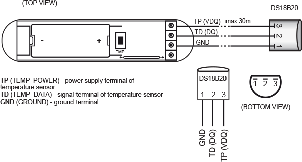
Hello I connect DS18B20 sensor in a universal module, but don't show temperature sensor, only display move sensor. ANT ..... GND - GND DS18B20 TD - DATA DS18B20 TP - VCC DS18B20 . . . GND - ( - ) P - (+) 12V Can someone help me Thanks Marcos
-
Hi. All DS18B20 all have unique IDs. Is there a way to see/read out that ID somewhere? ...or is there another way to identify which sensor is which?? "without touching or heating/cooling a specific sensor and monitoring the temperature?" I can not physically get to the sensors which are embedded in the floor! Any suggestions are welcome Thanks Jurgen
-
Hi, the reported values of my DS18B20 sensors are not very accurate. They are 1.5C° up the reality. When i measure the voltage on TD wire I only have 2.3V not 3.3V as indicated in the universal sensor data sheet. the module is powered 12V 1.5A supply. This device has not parameters to adjust the offset... Thanks for your help.
-
Dear All, I get a question - can I connect DS sensors as shown on below picture with using USB? Problem is that I get only 2 wires from sensor location to place where I can get UBS device. BR PBr

-
I found a very curious bug with the ZW5 version (version >=3.2) of the FGK-101+DS18B20 temperature sensor. When explicitly requiring a temperature report [thru "Sensor Multilevel Get" -> "Sensor Multilevel Report" commands], the actual temperature value reported via the ++synchronous++ Sensor Multilevel Report answer is buggy : +/- 0.5 to +/- 1°C random error from the correct temperature value; the variable size of the error is similar to what you would expect using only 8 bits of resolution from the DS18B20 measures. But when the FGK-101 itself sends an ++asynchronous++ report, after setting parameter#51 "Temperature reports threshold" to 3/10 °C and parameter#52 "Interval of temperature reports" to 4hours, then the temperature reported by the SAME Sensor Multilevel Report() from the SAME FGK-101+DS18B20 is correct !?. Note that parameter#50 "Interval of temperature measurements" is set to 60 seconds, which precludes such large variations in so little time; I also tried setting it to 5 seconds, no difference. I found this problem while developing a FGK-101\ZW5 handler for the SmartThings platform, but I would expect this bug to be present as well with the Fibaro Home Center 2... unless Fibaro uses some "hidden parameter" which corrects this bug. At that point, I have no idea how to correct this bug, except by removing from my handler all "Sensor Multilevel Get()" synchronous temperature requests, and relying only on asynchronous notifications. Interestingly, the correct asynchronous Sensor Multilevel Reports come CRC16-encoded, while the buggy synchronous ones come in clear. That suggests to me 2 different branches of code inside the FGK-101 firmware, but does not help me to workaround this extremely curious bug... And the same handler works fine with the older FGK-101 (version <=2.5). While I expect the same bug to exists when pairing the FGK-101\ZW5 to a Fibaro Home Center 2 controller, I would still be interested in getting a confirmation, which would definitely exclude the SmartThings hub from the list of suspects. Any help or suggestion greatly appreciated : this has been driving me crazy for days !
-
 Does anybody know the ACTUAL resolution programmed into the DS18B20 chip when inserted into the ++ZW5++ version of the FGK-101 ? The resolution of this chip is programmable at power-on to 9, 10, 11 or 12 bits, giving respectively 0.5, 0.25, 0.125, 0.0625°C increments. With the pre-ZW5 versions of the FGK-101, the resolution was clearly 12 bits, which happens to be the DS18B20 default resolution at power-on. But using the ++ZW5++ version of the FGK-101, with the SAME Device handler, I get DISCONTINUOUS readings, for instance 22.4, 22.8, 23.1, 23.4, 23.8°C, but NEVER values in between, such as 23.5, 23.6, 23.7°C for instance. This is consistent with a 0.25°C / 10 bits resolution only, which would be a major regression compared to the 12 bits of the pre-ZW5 FGK101+DS18B20. And AFAIK, there is no customizable parameter which would allow me to force 12 bits resolution back. Note that since all FGK-101 temperature parameters (51, 53, 55, 56) are given with 0.1°C quantum, only a 12 bits resolution is consistent with those parameters.
 -
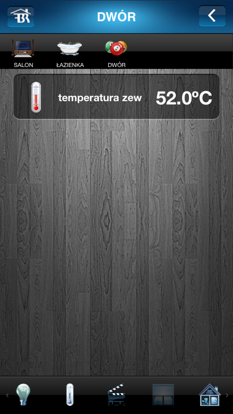
I've got a Fibaro D/W sensor to which I attached an external temperature sensor Dallas DS18B20 - temperature is changing accordingly - from 12 C to 127 C The sensor gives me a temperature that's higher than expected and it is correctly connected. It's seems that figures are OK when i change decimal point - is it possible? The temperature hold decimals - there should be a comma after the first digit - it's not 52 C but 5,2 C Can I make a VD with proper value ?

-
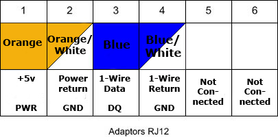
I bought an DS18B20 to my Fibaro Door/Windows sensor. And now I'm not sure how to configure The DS18B20 (that's on a cable with RJ12) Can anyone be kind and describe how to use it. External temp sensor and Fibaro Door/Window sensor. I have attached two photos, one how cable connected to the RJ12 and the other one is how to connect to the Fibaro can anyone help me with how to connect the DS18B20 to the Fibaro, where to connect what color. Thanx

-

Czujniki temperatury DS18B20 do Fibaro UBS - magistrala
midi posted a question in Universal Binary Sensor
Witam, do modułu UBS chcę podłączyć 4 czujniki DS18B20 do jednej magistrali podpiętej do modułu UBS Figaro. Całość zgodnie z zaleceniami chcę poprowadzić jednym, trójżyłowym, cienkim przewodem (typu drut) zachowując topologię magistrali (zamiast niezalecanej gwiazdy). Cała magistrala będzie miała ok. 10m, a czujniki będą na końcowym odcinku magistrali wpięte w nią mniej więcej co 1m. Czujniki jednak muszę trochę dla estetyki i minimalizacji odsunąć od przewodu magistrali. I pytanie zasadnicze: czy będzie poprawnie jeśli do przewodu magistrali wlutuję dodatkowe fragmenty ok. 20 cm przewodu aby czujniki oddalić trochę od samej magistrali (unikając prowadzenia podwójnego przewodu do 3 z 4 czujników)? Nie pojawią się przez to jakieś zakłócenia i odbicia sygnału na magistrali 1-wire? Czy takie połączenia zrobić lepiej lutowane czy zaciskane/skręcane? Może pytania są dla Was banalne, ale instalację chcę wykonać hobbystycznie i jestem jeszcze amatorem, a nigdzie w dokumentacji ani w google nie znalazłem sugestii. Są oczywiście przykłady, że te czujniki działają również w topologii gwiazdy, ale wolałbym nie mieć w przyszłości żadnych zakłóceń - zwłaszcza, że przewody puszczam w miejscu mało dostępnym. Pozdrawiam -
 Witam! Ma ktoś pomysł jak wirtualkę zmusić żeby symulowała główny czujnik temperatury? Z różnych powodów nie chcę korzystać z UBS, kontaktronów i innych urządzeń wykorzystujących dallasy DS18B20 do pomiaru temperatur. Za to mam wirtualkę która sczytuje dane z czujników innego systemu i ich wyniki zapisuje w zmiennych globalnych. Czy jest możliwość zmusić HC2 żeby korzystała ze zmiennej globalnej lub bezpośrednio z wirtualki jako głównego czujnika temperatury, wilgotności lub światła? A jeszcze lepiej żeby te dane przypisać go konkretnych pomieszczeń. Liczę na Waszą inwencję
 -

Temperature sensor and relay as thermostat
Stealth posted a question in Other Devices / Third-party devices
I'm having an issue with getting the Heating Panel to work! I have the following modules - 1) Fibaro Universal Module FGBS-001 2) Fibaro FGS-211 Relay Module 3) Dallas DS8b20 Temperature sensor I want to use these parts as a thermostat to control my hot water boiler. (i.e. temperature sensor on the hot water tank, when temperature drops below a threshold (between certain times of the day) the relay will answer the call for heat at the boiler by switching it on) I have added these modules to the HC2 but I am having problems trying to get them to be controlled by the heating panel. This is what I have done - a) I put the temperature sensor and the relay in a room named 'Water Tank' b) I have linked the temperature sensor and relay in the linked devices panel and named it Linked Hot Water c) I created a zone in the heating panel named 'Heat Control' then added the room 'Water Tank' to it d) I then set the temperature required with the day and time in the 'Heat Control' zone panel. But when the water temperature drops below the threshold set the relay won't switch on. What have I missed? Thanks -
I have a Fibaro binary sensor with a DS18b20 connected for reading temperature. I'm concerned that if the temperature sensor gets disconnected or fails the temperature sits at the last read level. This is a problem for me as any heating could remain on if it fails when the reading is low and heat is called for. Is there a way I can I can configure the sensor to fail to a error state, say to 255 deg C? Thanks


.png.768160ee01dbbe174110104157bee4fb.thumb.png.2f787c50bd6b3ae8e8215c35a85a4235.png)