Welcome to Smart Home Forum by FIBARO
Dear Guest,
as you can notice parts of Smart Home Forum by FIBARO is not available for you. You have to register in order to view all content and post in our community. Don't worry! Registration is a simple free process that requires minimal information for you to sign up. Become a part of of Smart Home Forum by FIBARO by creating an account.
As a member you can:
- Start new topics and reply to others
- Follow topics and users to get email updates
- Get your own profile page and make new friends
- Send personal messages
- ... and learn a lot about our system!
Regards,
Smart Home Forum by FIBARO Team
Search the Community
Showing results for tags 'wiring'.
Found 17 results
-
Hi everyone, I’d like to add a Fibaro Smart Implant (FGBS-222) in parallel with an existing 24 V momentary wall switch that controls my shutters. The wall switch currently takes a 24 V supply and, when pressed, sends 24 V to terminal 2A (open) or 2B (close). Current idea My plan is to power the Smart Implant from the same 24 V supply as the wall switch/controller (P = +24 V, GND = 0 V). The Smart Implant’s relay outputs would then “simulate” pressing the wall switch by switching +24 V onto the same control terminals: P → +24 V supply GND → 0 V / GND OUT1 → 2A (open) OUT2 → 2B (close) Inputs (IN1/IN2) would remain unused. The Smart Implant documentation says it can control devices by opening/closing its output contacts independently of inputs, and it supports a 9–30 V supply, so powering it from 24 V should be fine. Wiring question (OUT1/OUT2) What I’m unsure about is the relay wiring detail: is it sufficient to connect only a single wire from OUT1 to 2A (and OUT2 to 2B), assuming the other side of those outputs is internally referenced, or do I need to wire a return/common as well? (From other Smart Implant examples, it seems the external circuit typically needs a complete loop through the relay contact, i.e., the relay closes between a “common” and the target input, but I’m not 100% sure how that maps to my shutter controller terminals.) Configuration question If inputs stay unused, what parameters should be changed so the outputs behave like a momentary button press (short pulse), rather than staying on? From the parameter list, it looks like I should use the output “auto off” timers so OUT1/OUT2 switch off automatically after a short time (pulse), but I’m unsure what value is recommended for shutter controller inputs. Any feedback? Does the approach (powering from 24 V and using OUT1/OUT2 to drive 2A/2B) make sense electrically? For the relay outputs: do I need to wire an additional GND/common to the output side to complete the circuit? Which output settings (especially auto-off / pulse duration) are typically used for this kind of shutter control? If anyone has done something similar (Smart Implant + 24 V shutter controller / momentary switch in parallel), a quick wiring sketch or parameter guidance would be greatly appreciated.


-

Wire Dimmer 2 with unattended switches (Live directly to switch)
odelrio posted a question in Dimmer and Bypass
Hello: I think that my scenario is very common, but I can't find or can't understand how to wire it. In the junction box where I'm installing the Dimmer 2 (FGD-212) I have Live, Neutral and the end of a 4-way switches circuit that works with Live. My switches are toggles, not potentiometers (wheels). I want to dim the light only remotely and to use the physical switches to turn the light on and off. I see no reason to power my switches from Sx. I can't understand the 2-wire or 3-wire schemas in the manual. Why is Neutral connected to Sx sometimes? Isn't Sx the Live output for the switches? Can I power the switches directly from Live and then feed S1 with it? See the attached schema. Thank you!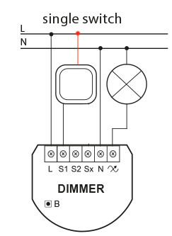
-
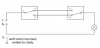
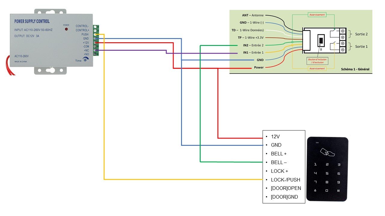
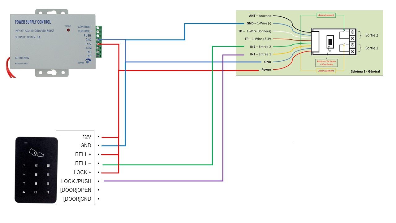
Hello, I started to install a rfid keyboard with a FGBS01 to make a keyboard for the alarm. I installed, wired and configured everything, but.... it doesn't work.After 2 days of tearing my hair out, I came for help ? I suspect an error in my cabling that is below: > Drawing A My objective is - use the bell button to include it in an arming scene - use the code to disarm. But here it is, when I set the IN1 input to Binary NC (or NO for that matter) it doesn't detect a change of state. And at the doorbell I have almost nothing that passes (0,6V ????) So I've revised my wiring and I'm thinking of doing this, but I hesitate between these two solutions: > Drawing B1 or > Drawing B2 Is either of these two solutions good? Anyway, I think my wiring is not good. And by dint of trying everything, I changed the configuration in the HCL 20 times. You will have understood it, I am lost, and by dint of trying everything that was going through my head I am completely in the fog now. Thank you for your help


-
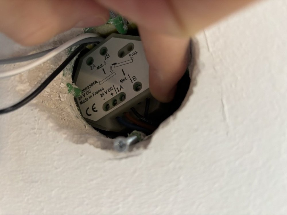
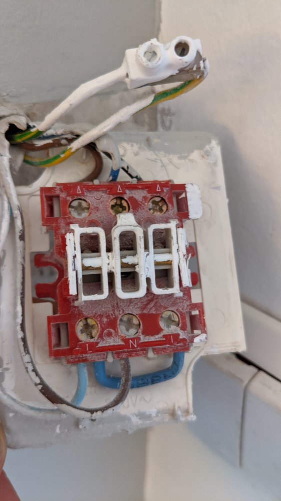
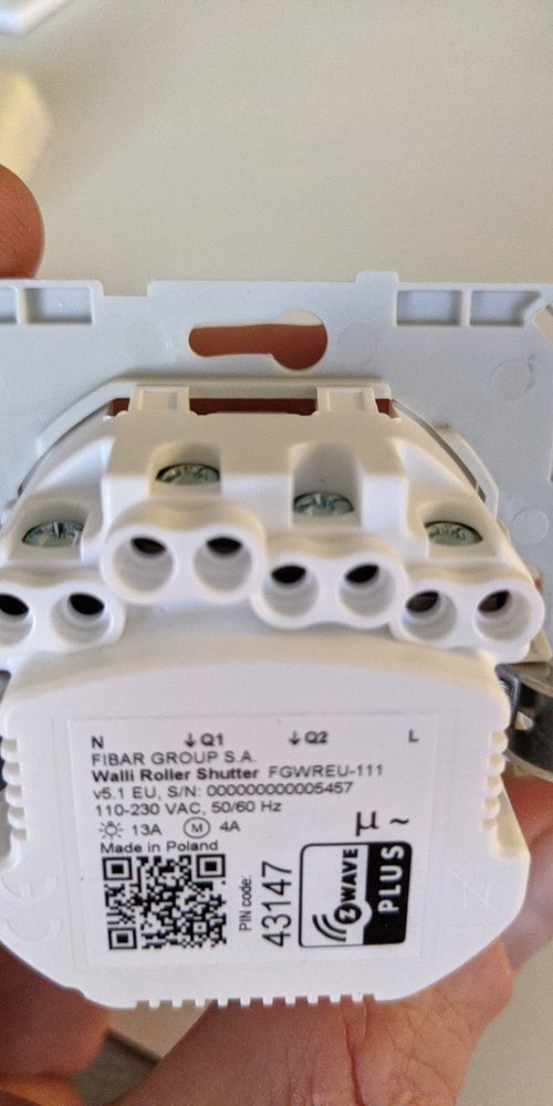
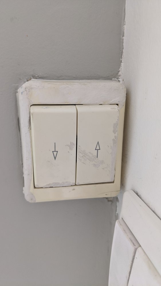
Dear community. I'm switching my dumb roller shutter with a walli. The guide doesn't seem to cover my existing wire layout. How do I connect these? I'm in Norway, by the way.
-
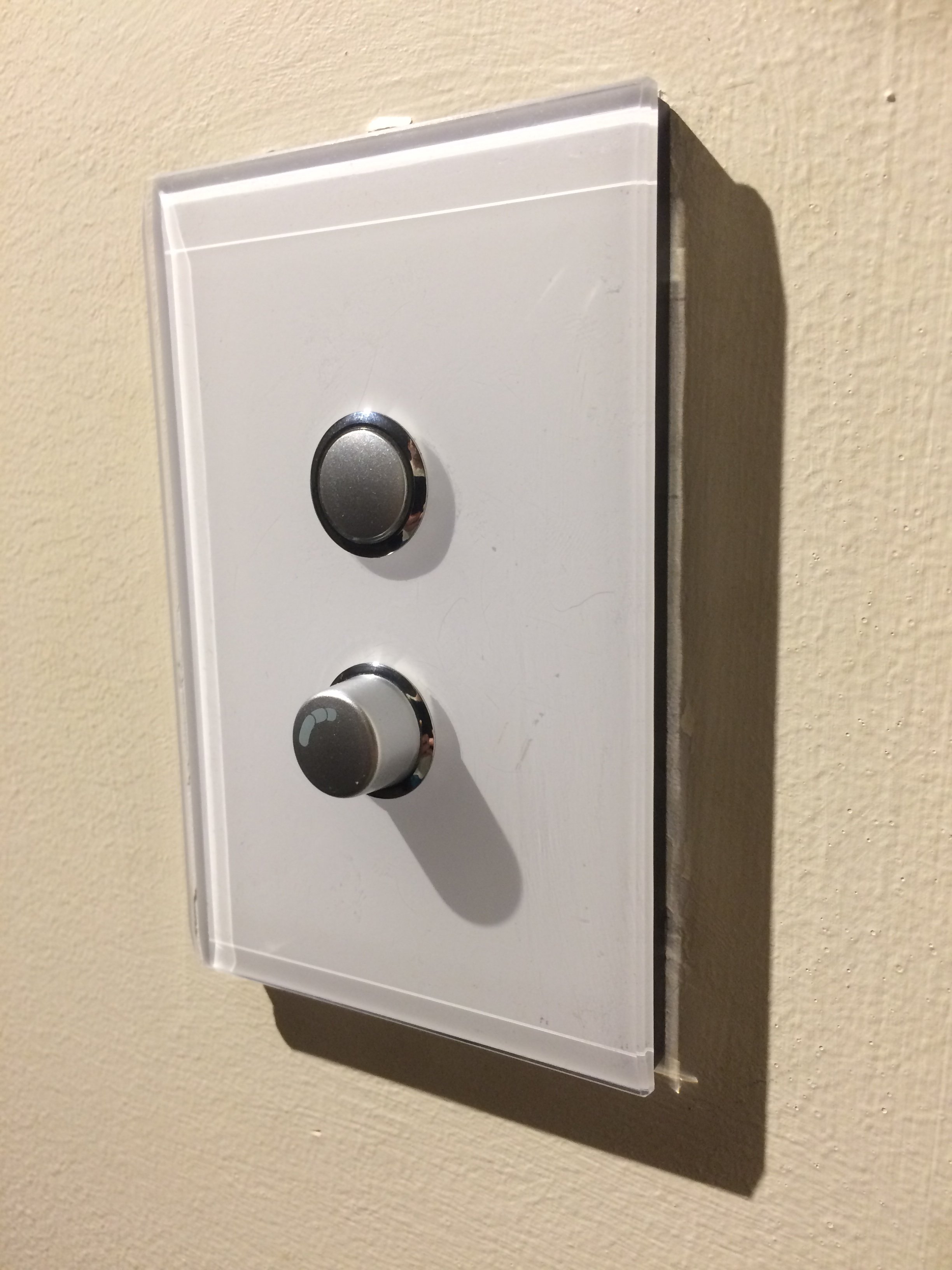
I’ve recently installed a Fibaro Dimmer 2 in-wall module in my dining room on a 2-wire electrical circuit. This has been set up to control the main light using the load control of the dimmer (switch 1) and the lamps using z-wave control (switch 2). This works perfectly (see image). I would like to add a third switch to control another z-wave device in the wall panel. Would it be possible to do this by wiring in another Z-wave module in series or something? I’ve attempted this with a spare in-wall dimmer, but can’t figure out how to get it working on a 2-wire circuit like this one – perhaps it’s not possible. Any guidance would be really appreciated. See image for current working setup (two switches). Thanks!
-
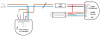
 Hi all, I’m trying to wire a Guardline Driveway Motion sensor’s output to a Fibaro Universal sensor, and wondered if anyone who’d done it before could help me out please? My idea for how to do it is below, the colours i’ve used have no relevance to the coloured cables of Fibaro. Top is the Fibaro and bottom the Guardline device. What do you think?
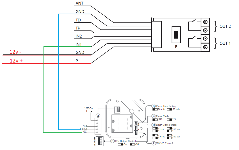
-
Hi hellow Im new in fibaro. can someone help me to wire my roller blind in roller shutter control. my shutter had 3 wires only. earthquake, live(hot wire) and neutral. how to wire it. thanks for the help.
-
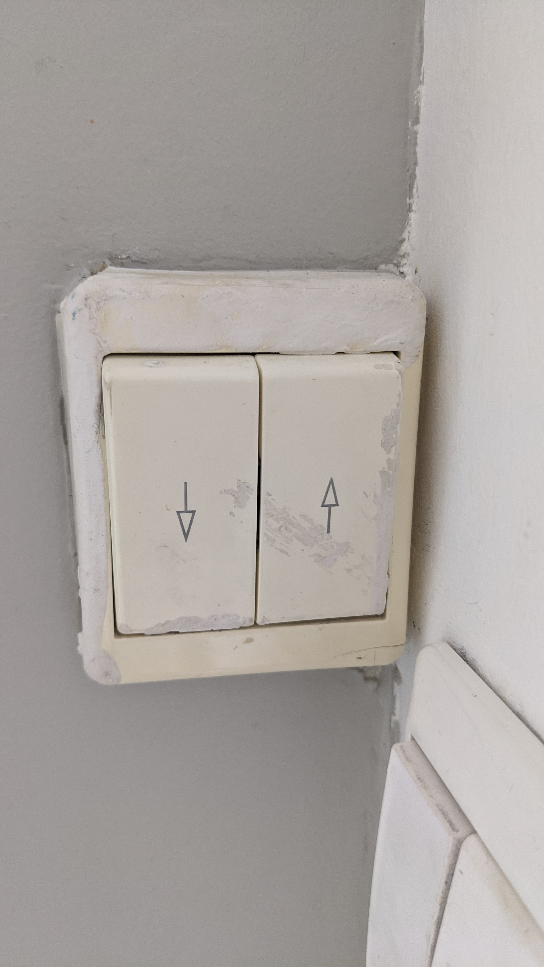
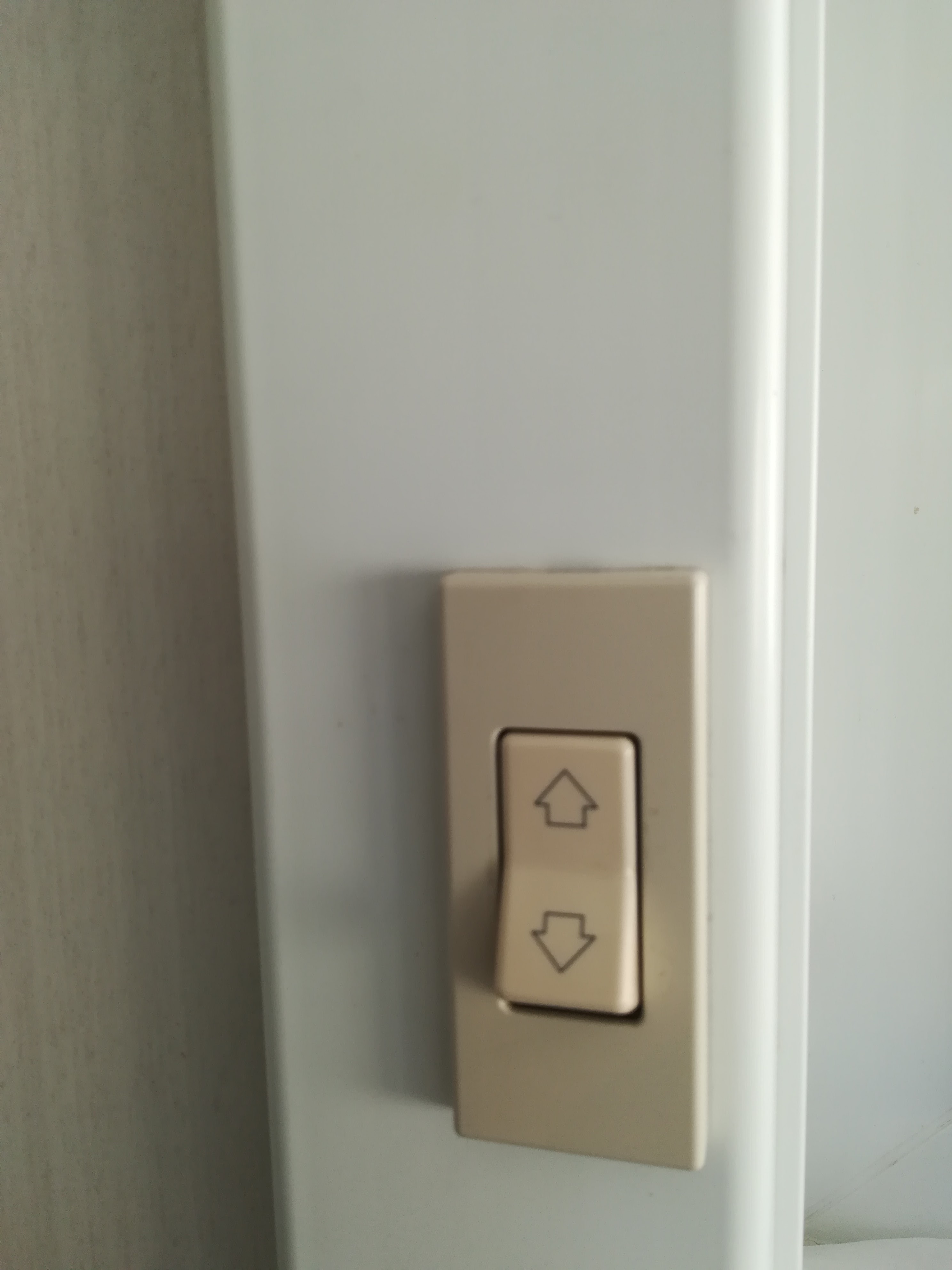
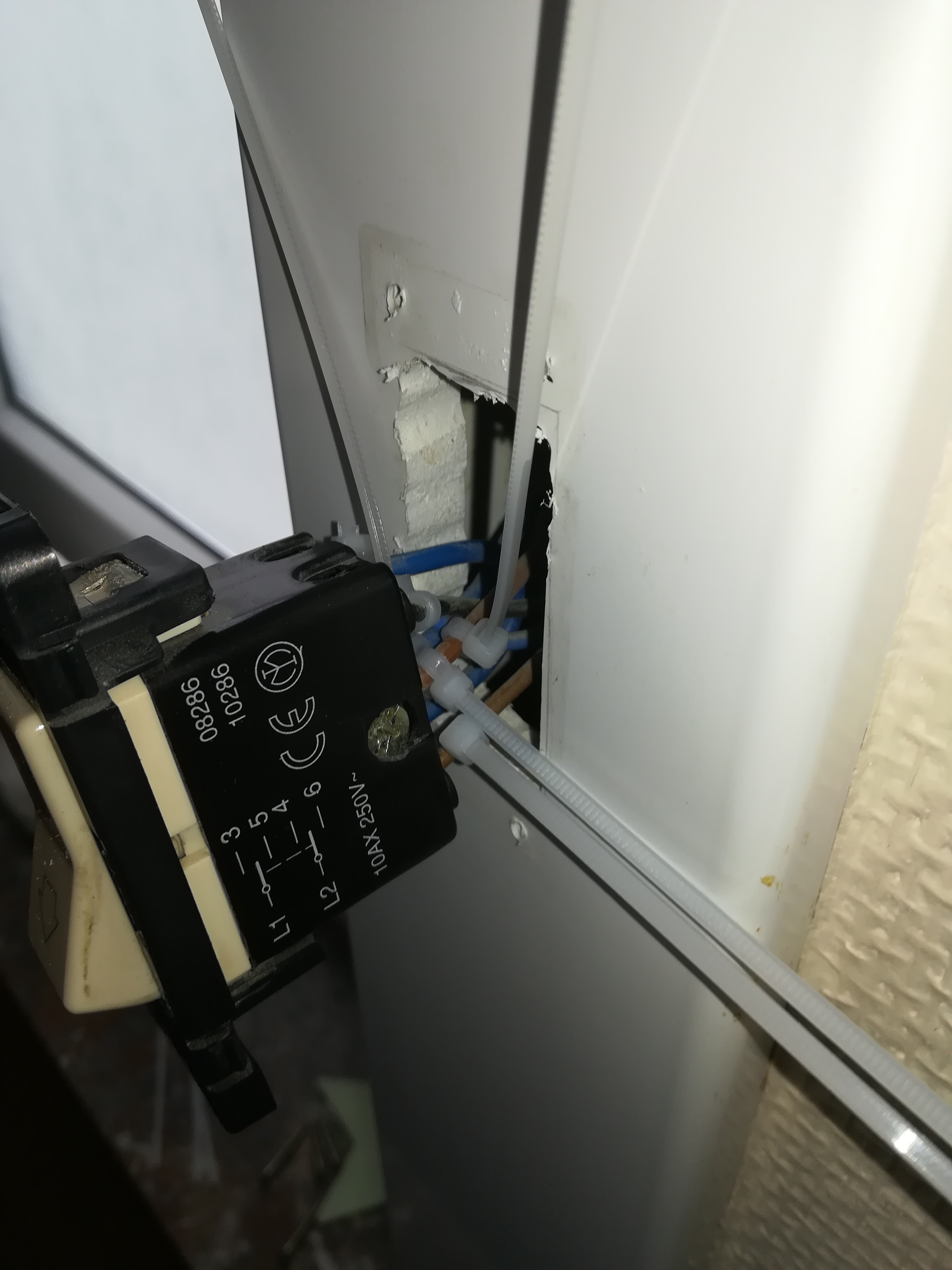
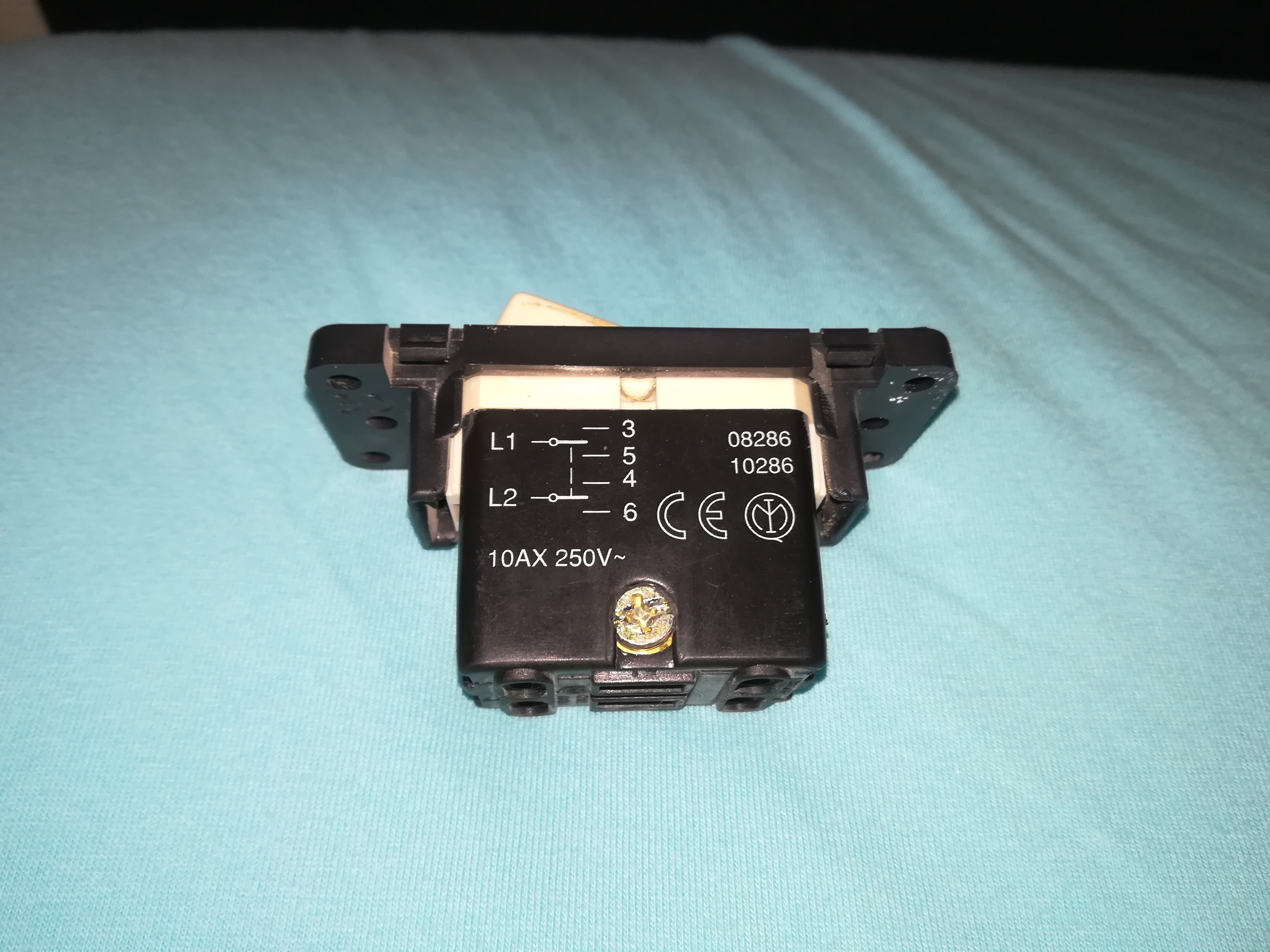
Hi, My name is Dave and I'm new here. I have five Windows with electic roller shutters. I want to use the Roller Shutter v2 from Fibaro to automate these things. But I'm not sure if I will be able to connect the exesting switch to the system. The regular swithes uses three wires but mine has six wires. Please find attached some pictures. I there someone who can help in this matter ? Thx, Dave


-
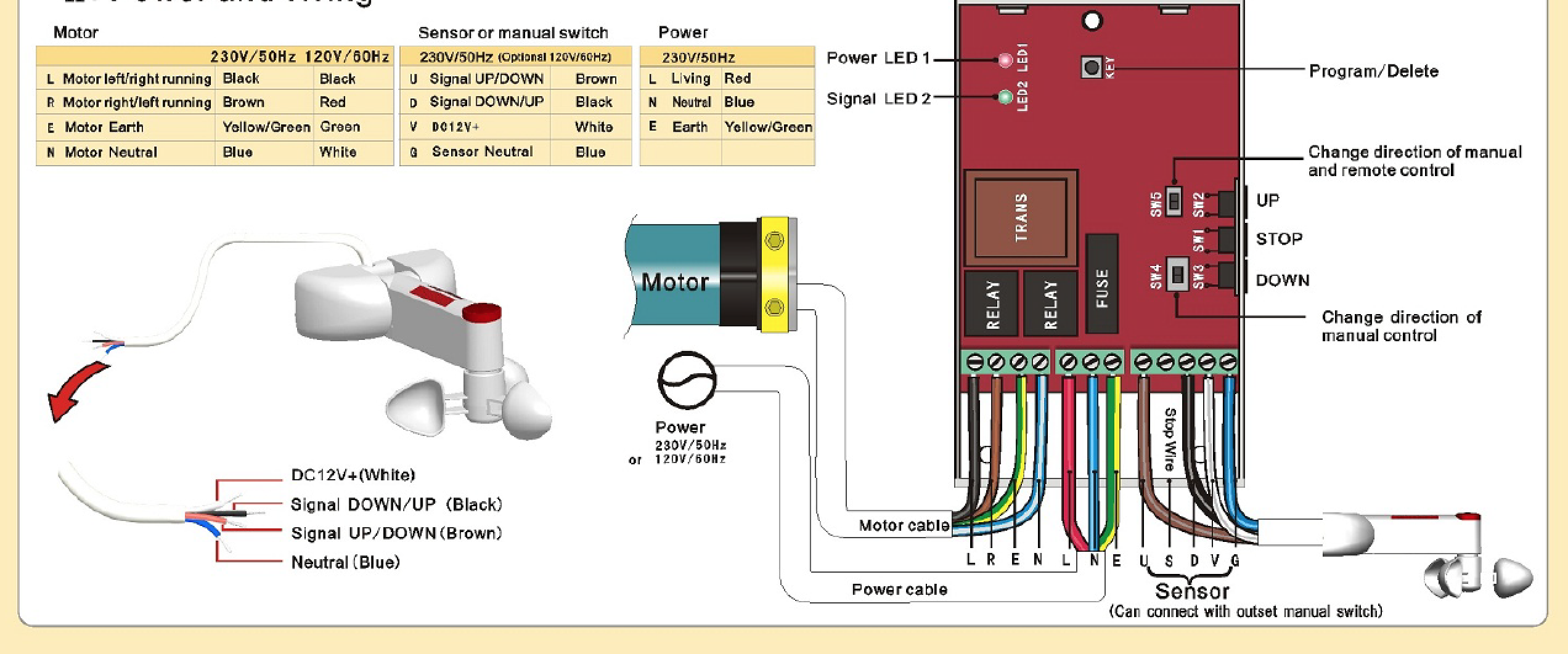
Hi Guys, I recently purchased an awning and would like to connect it to our Fibaro system. I already have blinds , curtains etc connected to HC2 so I'm pretty familiar with Roller Shutter 2. I purchased the awning with a stand alone receiver with wind, rain sensor (see attatched image). I looked at integrating the wind and rain sensors in Fibaro but My fibaro does crash from time to time so i like the idea of the wind and rain sensor acting independently (safe from crashes). If my curtains don't open because Figaro crashed - no big deal. If the awning stays open and gets ripped out of the wall because fibaro crashed - kind of a big deal!!! The receiver accepts the 4 wires for the awning, power input and control input from the sensor. So my plan was to wire a manual momentary switch for up and down into the Roller shutter 2 and connect into the up down inputs (Marked L & D on the picture) . Hopefully the best of both worlds - local , independent control from the receiver and integration with the HC My question is around power. Normally the power runs through the roller shutter 2. In this scenario i need power to run directly , permanently to the receiver box so the sensor remains active. So can I wire the power in parallell to the RS2 and the RS2 simply manages the up / down component? Or am I better using a dual relay for this purpose instead? If i do it that way I will lose positioning information in HC2? Thanks in advance for your assistance.

-
Hi Gurus! I've got a Clipsal universal dimmer & my sparky mate is struggling to wire that in with the Fibaro dimmer 2 (FD2). He's got the FD2 working ok without the Clipsal universal dimmer but can't get both. Can anyone give me a wiring diagram? Ideally without a neutral.

-
The guide about installing Single Switch 2 (http://manuals.fibaro.com/switch-2/) assumes that there are three cables inside the switchbox. However, my installation is missing ground ("earth") which may be because multiple switches control the same light. My apartment is rather modern since it has been constructed in 2016. Is it possible to install the single switch 2 without a ground cable? I have seen tutorials which do so with the dimmer (https://www.youtube.com/watch?v=OQ8oCvIPT4s) but I did not find any information about the switch. I was thinking of bridging N and Q1 (for the dimmer they bridge N and O), but since I did not find any information on it, I did not dare to try it. Can you give me some insight?
-
Hi guys, I'm currently renovating an old building and will be installing Fibaro modules for all the lights and shutters. Since I want to install lots of switches it's getting difficult to put all the wires + a module behind a switch (some switches will have15 wires + module behind them). I'm considering to place some modules on top of the "fake ceiling" to save some place behind the switch. Do you guys have any other suggestions (tips or tricks) to lessen the amount of wires behind a switch? Thanks!
-
Hi, i'd like to use the Rely Switch to control two lights, but cannot work out how to wire the thing ! The two light switches are on a combined light switch/power outlet. To each switch is only one wire, the black one. These I assume go to the S1 ans S2 connections. The blue and brown, live and neutral go to L and N connections. After that I'm a bit stumped ! Any help would be much appreciated. I've made a diagram of the wiring as it is now. Thanks.

-
For a number of my ceilings I have the 24V transformers and Fibaro RGBW controllers in the loft and a piece of CAT6 cable wired into the RGBW terminals and fed down into each bedroom. Once in the bedroom the electrician crimped the CAT6 cables on to the RGBW strip lead cables. Worked great. However, all my LED strips had a fault after about 6 months and I'm having to go round replacing them all (all under warranty thankfully!). Whilst replacing I'm removing the crimp butts. What I'd like to do is replace the crimp butts with a plug & socket combo so if I ever need to remove them again in the future it's easy. The traditional plastic terminal blocks are too bulky in my ceiling space. The Wago connectors aren't practical for 5 wires. There's a fair bit of amperage going through the cable when I bang them up to full RGBW bright white managed to melt one of my plastic terminal blocks as it was (stupidly) only 3A safe (!) So I'm looking at other connector options such as ones found in PC hardware: 5 pin SATA connectors - https://www.moddiy.com/products/5%2dPin-SATA-Connector-w{47}-Pins-%2d-Black.html PWM Fan Connector x 2 - https://www.moddiy.com/products/modDIY-Female-4%2dPin-(3%2b1)-PWM-Fan-Connector-(Molex-%232510)-with-Pins.html 6 pin PCi Express connector - https://www.moddiy.com/products/6%2dPin-PCI%2dExpress-Power-Female-Connector-w{47}-Pins-%2d-Black.html But none of these really tell me how much power they can stand before melt down :-S Would appreciate any suggestions from experts
-
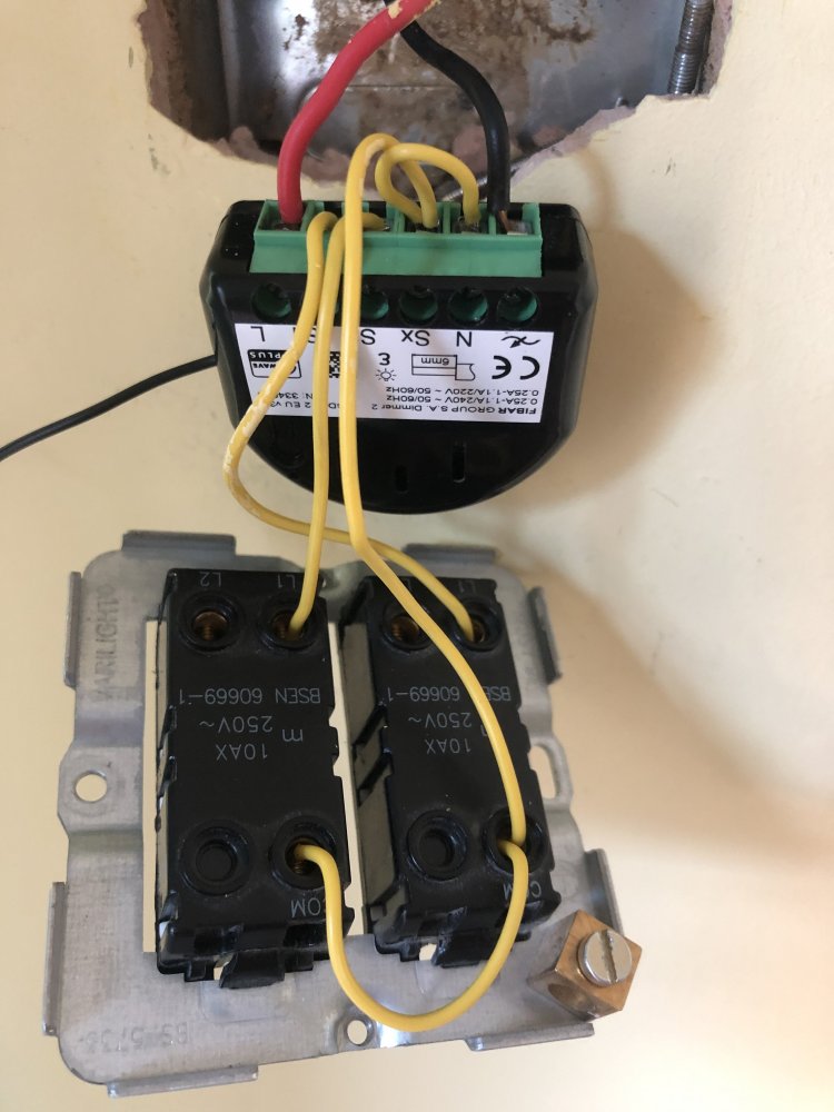
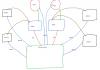
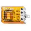
Hi, thank you in advance for your patience and hopefully support. I'm a good programmer, I've limited electrician skills but I successfully installed 4 fibaro roller shutters following online tutorials and done some other small electric changes in my home Now I would like to modify my electrical system adding one Fibaro double relay switch, in order to remotely control two lamps. Actually each lamp is controlled by two push buttons and one Finder Relay like this one On each button there are 2 wires attached: 1 common neutral and 1 wire attached to the Finder relay. What I would like to achieve: replace the two Finder relays with one Fibaro Double Relay in the electric box, and have all 4 buttons still working. Do you think this is possible? I attach also a draw made by me with my actual system. If this is possible, do you have some hints for needed wiring? Sorry for my non-technical schema Thanks in advance for your time Best regards
-
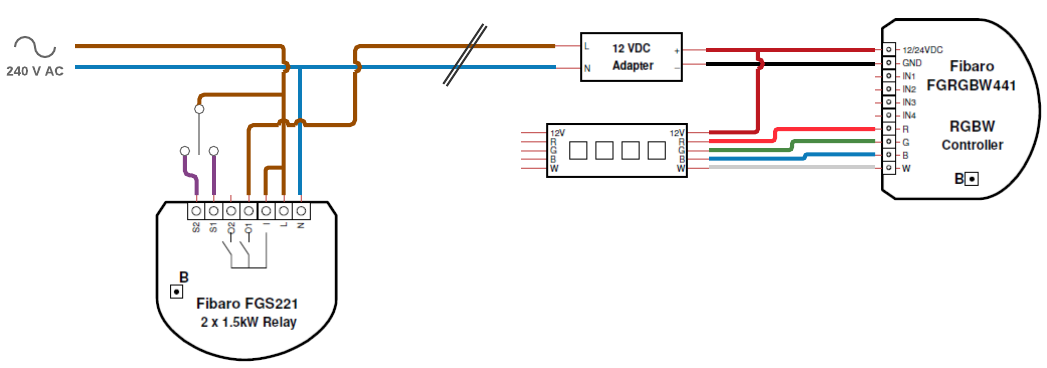
Hi all! Very new to Fibaro but excited about what I can do!.. Am planning the installation of some RGBW LED strips and could do with some help regarding the wiring. I currently have a wall switch running across the room to a standard tungsten light. I want to remove this light, connect my 12v transformer, RGBW Fibaro module and LED strip. This sounds simple, but I'm not sure if I have the wiring right. I just want one switch and can't easily install any new cabling to the LED. Am happy that the switch just turns the LED on and off (ideally to its previous brighness/colour setting), with colour control via the app. See attached for what I'm proposing with the use of a relay module and 3-way momentary/retractive switch. Will this work (momentary switch to S2 = on, momentary switch to S1 = off)? Not sure of the impact on the RGBW module if power is removed? Is there a better way? Obviously I should just connect the switch to the RGBW module IN1 terminal, but this would require additional wiring from the switch to the transformer/module! Thanks, Fergie
-
Hello! I've purchased an FGD211 Dimmer module but I'm having some trouble making up the required connections for my lighting installation. What is confusing me is that I cannot map my lighting installation to any of the diagrams in the instructions. Also, any other diagram I find online regarding dimmer installations seems to assume there are three cables connecting the two switches - I only have two cables connecting the switches. You can find my lighting installation wiring diagram in attachment. Thanks in advance for any help you might give me. Best regards!